Specifications
|
Programming accuracy (at 23 °C ± 5 °C)
|
AC6903H 5 kHz
AC6903L 550 Hz
|
AC6906H 5 kHz
AC6906L 550 Hz
|
AC6912H 5 kHz
AC6912L 550 Hz
|
AC6918H 5 kHz
AC6918L 550 Hz
|
|
Output
AC1
|
|
AC voltage 2 (Low range
/ High range)
|
160 V / 320 V
|
|
Setting range
(Low range / High range)
|
0.0 ~ 161.0 V / 0.0 ~ 322.0 V
|
|
Resolution
|
0.1 V
|
|
Accuracy 3, 4 (Low range/High range)
|
± (0.15%
+ 0.3 V) (45
Hz - 500 Hz)
|
|
± (1%
+ 0.3 V) / ± (1% + 0.6 V) (500
Hz - 5 kHz)
|
|
Max
rms current 5
|
|
|
1P (Low range
/ High range)
|
30 A / 15 A
|
60 A / 30 A
|
120 A / 60 A
|
180 A / 90 A
|
|
1P3W or 3P (Low range
/ High range)
|
10 A / 5 A
|
20 A / 10 A
|
40 A / 20 A
|
60 A / 30 A
|
|
Power
capacity
|
|
|
1P or 3P
|
3 kVA
|
6 kVA
|
12 kVA
|
18 kVA
|
|
1P3W
|
2 kVA
|
4 kVA
|
8 kVA
|
12 kVA
|
|
Load power factor
|
0~1 (leading or lagging)
|
|
Frequency
|
|
|
Range 6
|
1 Hz~5 kHz (5 kHz -3 dB, < 40 Hz power
de-rating is required)
|
|
Resolution
|
0.01Hz (1.00
Hz~99.99 Hz),
0.1Hz (100.0 Hz~999.9 Hz),
1 Hz (1 kHz~5 kHz)
|
|
Accuracy 7
|
± 0.01%,
temperature coefficient:± 0.005%/℃
|
|
Phase
|
1P (single-phase), 1P3W
(single-phase three wire)
|
|
3P4W (three-phase four-wire) switchable
|
|
Resolution
|
0.1° (waveform bank 0 and 1 Hz~500 Hz), 1° (500
Hz~4 kHz), 2° (>
4 kHz)
|
|
Accuracy 8
|
Within 120°±
(0.4°+fo×0.9°); fo = output
frequency (kHz)
|
|
Output
DC 1
|
|
DC voltage 9 (Low range
/ High range)
|
± 226
V / ± 452 V
|
|
Setting range
(Low range / High range)
|
0 to ± 227.5 V / 0 to ± 455 V
|
|
Resolution
|
0.1 V
|
|
Accuracy
|
± (0.15%
+0.3V)
|
|
Max current 10
|
30 A / 15 A
|
60 A / 30 A
|
120 A / 60 A
|
180 A / 90 A
|
|
Power capacity
|
3 kW
|
6 kW
|
12 kW
|
18 kW
|
|
Parallel operation
|
|
Maximum number of units in parallel operation
|
-
|
N (units
in parallel) ≤ 4
|
N (units
in parallel) ≤ 4
|
N (units
in parallel) ≤ 4
|
|
Maximum power
capacity 11
|
3 kW
|
[Capacity of one unit] x N
|
[Capacity of one unit] x N
|
[Capacity of one unit] x N
|
1. Combined with AC and DC output,
the peak voltage
must be between -455 V to 455 V (High range) or -227.5 V to 227.5 V (Low range).
2.
The specified guaranteed voltage range is 1 V to 160 V and 2 V to 320 V.
3. At no load, the response is in FAST or MID, using the compensation function.
4. At the phase angle of 120° for each phase for line voltage.
5. The maximum
rms current is associated with the output
voltage range. When the output voltage is between 100 VAC and
160 VAC or 200 VAC and 320 VAC, the output voltage reduces
the output current.
When the output frequency is between 1 Hz and 40 Hz, the output frequency reduces
the output current.
The output current
is 70% at 1 Hz.
6.
L models – the frequency is 1 Hz to 550 Hz for three-phase
output.
7. Temperature coefficient applies when the environmental temperature is beyond 23 °C ± 5 °C. Example:
At temperature 30 ℃
and setting frequency
1 kHz, frequency accuracy = 1 kH±0.002
kHz. (±0.01%+0.005%/℃×2 ℃=±0.02%).
8. Example: Performance of angle conversion at a given frequency within
120° ±0.5° at 60 Hz output, within 120° ±0.8° at 400 Hz output.
9.
The guaranteed voltage
range is 1.4 VDC to 226 VDC and 2.8 VDC to 452 VDC.
10. The maximum
rms current is associated with the output voltage range. When the output voltage
is between 100 VDC and 226 VDC or 200 VDC and 452 VDC, the output voltage reduces
the output current.
11. The maximum
rating is limited
to 48kVA for single -phase
and 72kVA for single-phase three wire, regardless of the number of units in parallel
.
|
Measurement accuracy (at 23 °C ± 5 °C)
|
AC6903H 5 kHz
AC6903L 550 Hz
|
AC6906H 5 kHz
AC6906L 550 Hz
|
AC6912H 5 kHz
AC6912L 550 Hz
|
AC6918H 5 kHz
AC6918L 550 Hz
|
|
Measurement
|
|
AC voltage resolution
|
0.1 V
|
|
AC voltage accuracy
|
± (0.03% + 100 mV) (45 Hz~100 Hz)
± (0.1% + 100 mV) (100 Hz~999.9 Hz)
± (0.5% + 1 V) (1 kHz~5 kHz)
|
|
rms current resolution
|
0.01 A
|
0.1 A
|
|
rms current accuracy 1
|
± (0.15% + 0.2% of fs) (45 Hz~65 Hz)
± (0.5% + 0.5% of fs) (DC,
40 Hz~999.9 Hz)
± (1.2% + 1.2% of fs) (1 kHz~5 kHz)
|
|
Peak current resolution
|
0.01 A
|
0.1 A
|
|
Peak current accuracy 2
|
4% of full scale
|
|
Active power
resolution
|
1 W
|
10 W
|
|
Active power
accuracy 1, 3
(Low range/High Range)
|
± (0.7% + 0.7% of fs + 0.001%
of fs/V) / ± (0.7% + 0.7% of fs + 0.0005% of fs/V) (45
Hz~100 Hz)
|
|
Apparent power
resolution
|
1 VA
|
10 VA
|
|
Apparent power
accuracy 1, 3
(Low range/High Range)
|
± (0.3% + 0.3% of fs + 0.001%
of fs/V) / ± (0.3% + 0.3% of fs + 0.0005% of fs/V) (45
Hz~100 Hz)
|
|
Power factor
resolution
|
0.01
|
|
DC Voltage resolution
|
0.1 V
|
|
DC Voltage accuracy
|
0.05% + 150 mV
|
|
Output
stability
|
|
Line regulation 4
|
±0.1%
|
|
Load regulation 5, 6
(Low range/High Range)
≤ 100 Hz
≤ 500 Hz
≤ 1 kHz
|
± 0.1 V / ± 0.2 V
± 0.3 V / ± 0.6
V
± 1 V / ± 2 V
|
± 0.2 V / ± 0.4
V
± 0.3 V / ± 0.6
V
± 1 V / ± 2 V
|
|
Total harmonic distortion 6
|
0.3% (≤ 100 Hz),
0.5% (≤ 330
Hz), 1.5% / kHz (≤ 5 kHz)
|
1. At 10 % to 100 % of maximum
rated current; sine wave. fs = full scale.
2. Pulse height
of sine wave.
3. Power factor
of 1.
4. For input voltage changes
within the rated range.
5. For output
current changes within
0 to 100 % of the rating
when not using the compensation function.
6. When the output phase voltage is 80 V – 160 V (Low range) or 160 V – 320 V (High range), the load power factor is 1, and the response
is FAST at the output terminal block
Supplemental characteristics
Supplemental characteristics AC6903H 5 kHz
AC6903L 550 Hz
AC6906H 5 kHz
AC6906L 550 Hz
AC6912H 5 kHz
AC6912L 550 Hz
AC6918H 5 kHz
AC6918L 550 Hz
|
Output
|
|
Max peak current 1
|
4 times the maximum
output current
|
|
Inrush current capacity
|
Current at 1.4 times
the maximum output
current for 0.5 s
|
|
Temp coefficient 2
|
100 ppm / ℃
|
|
Transient response 3
|
40 μs (Fast)
|
|
Response speed
Tr/Tf 4
|
40 μs (Fast), 100 μs (Medium), 300 μs (Slow)
|
|
Ripple noise
5
|
0.25 Vrms
|
0.3 Vrms
|
0.4 Vrms
|
|
Variation according to output frequency 6, 7
|
Output voltage correction function enable:
± 0.3% (1 Hz~1
kHz), ± 10%
(1001 Hz~5 kHz)
Output voltage
correction function disable: -3 dB (5 kHz)
|
|
Harmonics measurement
|
|
Fundamental frequency
|
10 Hz~1 kHz
|
|
Upper limit
harmonic
|
5th to 50th
|
|
Measurement items
|
Rms voltage and current
/ phase angle
THD
|
|
Current magnitude accuracy
|
0.15% + 0.20% of fs (Fundamental 50 Hz or 60 Hz)
1.2% + 1.2% of fs (Harmonics 2nd to 50th)
|
|
Output
impedance
|
|
1P
|
|
|
Low
|
Resistance
|
0 Ω to 667 mΩ
|
0 Ω to 333 mΩ
|
0 Ω to 167 mΩ
|
0 Ω to 111 mΩ
|
|
Reactance
|
Fast
|
13 µH to 667
µH
|
7 µH to 333
µH
|
3 µH to 167
µH
|
2 µH to 111
µH
|
|
Med
|
27 µH to 667
µH
|
13 µH to 333
µH
|
7 µH to 167
µH
|
4 µH to 111
µH
|
|
Slow
|
80 µH to 667
µH
|
40 µH to 333
µH
|
20 µH to 167
µH
|
13 µH to 111
µH
|
|
High
|
Resistance
|
0 Ω to 2667
mΩ
|
0 Ω to 1333
mΩ
|
0 Ω to 667 mΩ
|
0 Ω to 444 mΩ
|
|
Reactance
|
Fast
|
53 µH to 2667
µH
|
27 µH to 1333
µH
|
13 µH to 667
µH
|
9 µH to 444
µH
|
|
Med
|
107 µH to 2667
µH
|
53 µH to 1333
µH
|
27 µH to 667
µH
|
18 µH to 444
µH
|
|
Slow
|
320 µH to 2667
µH
|
160 µH to 1333
µH
|
80 µH to 667
µH
|
53 µH to 444
µH
|
|
1P3W
or 3P
|
|
|
Low
|
Resistance
|
0 Ω to 2000
mΩ
|
0 Ω to 1000
mΩ
|
0 Ω to 500 mΩ
|
0 Ω to 333 mΩ
|
|
Reactance
|
Fast
|
40 µH to 2000
µH
|
20 µH to 1000
µH
|
10 µH to 500
µH
|
7 µH to 333
µH
|
|
Med
|
80 µH to 2000
µH
|
40 µH to 1000
µH
|
20 µH to 500
µH
|
13 µH to 333
µH
|
|
Slow
|
240 µH to 2000
µH
|
120 µH to 1000
µH
|
60 µH to 500
µH
|
40 µH to 333
µH
|
|
High
|
Resistance
|
0 Ω to 8000
mΩ
|
0 Ω to 4000
mΩ
|
0 Ω to 2000
mΩ
|
0 Ω to 1333
mΩ
|
|
Reactance
|
Fast
|
160 µH to 8000
µH
|
80 µH to 4000
µH
|
40 µH to 2000
µH
|
27 µH to 1333
µH
|
|
Med
|
320 µH to 8000
µH
|
160 µH to 4000
µH
|
80 µH to 2000
µH
|
53 µH to 1333
µH
|
|
Slow
|
960 µH to 8000
µH
|
480 µH to 4000
µH
|
240 µH to 2000
µH
|
160 µH to 1333
µH
|
1. Repeated output
is possible when the crest factor is four.
2. For changes
within the operating temperature range at output phase voltage 100 V / 200 V , no load.
3. When the output voltage
is 100 V / 200 V, the load pf is 1, and the output current
changes from 0 A to the rated value and from the rated value to 0 A.
4. At 10% to 90% of the output voltage.
5. 5 Hz to 1 MHz components are in DC mode.
6. The voltage
variation over 40 Hz to 5 kHz in AC mode with 55 Hz as the reference.
7. When the output phase voltage is 80 V to 160 V (Low range) or 160 V to 320 V (High range), the load power factor is 1, and th
e response is FAST.
|
Supplemental characteristics
|
AC6903H 5 kHz
AC6903L 550 Hz
|
AC6906H 5 kHz
AC6906L 550 Hz
|
AC6912H 5 kHz
AC6912L 550 Hz
|
AC6918H 5 kHz
AC6918L 550 Hz
|
|
Output
On / Off phase angle
setting
|
|
Setting range
|
0.0 degrees to 360.0
degrees (0.0 degrees
= 360.0 degrees)
|
|
Resolution
|
0.1 degrees
|
|
Accuracy 1
|
± 1 degree (≤ 1 kHz)
|
|
Input
|
|
Apparent power
|
≤ 4 kVA
|
≤ 7.8 kVA
|
≤ 15.6 kVA
|
≤ 23.4 kVA
|
|
Power factor
2
|
0.93 (TYP)
|
0.95 (TYP)
|
|
Efficiency 2
|
82% (TYP)
|
85% (TYP)
|
|
Hold-up time
for power
interruption 2
|
10 ms
|
|
Frequency (nominal)
|
50~60 Hz
|
|
Frequency (variation)
|
45~65 Hz
|
|
200V
input model
|
|
Voltage (nominal)
|
100 to 120 Vrms
/
200 to 240
Vrms
|
200 to 230 Vrms
|
|
Voltage (variation)
|
85 to 132
Vrms /
170 to 250
Vrms
|
170 to 250 Vrms
|
|
Phase
|
1P
|
3P3W
|
|
Max input current (rms)
3
|
48 A / 24 A
|
27 A
|
53 A
|
80 A
|
|
Protective conductor current 4
|
≤ 3.5 mA
|
≤ 10 mA
|
≤ 15 mA
|
≤ 20 mA
|
|
400V
input model
|
|
Voltage (nominal)
|
-
|
380 to 480 Vrms
|
|
Voltage (variation)
|
-
|
323 to 519 Vrms
|
|
Phase
|
-
|
3P4W
|
|
Max input current (rms)
3
|
-
|
14 A
|
28 A
|
42 A
|
|
Protective conductor current
|
-
|
≤ 3.5 mA
|
≤ 3.5 mA
|
≤ 3.5 mA
|
|
Mechanical
|
|
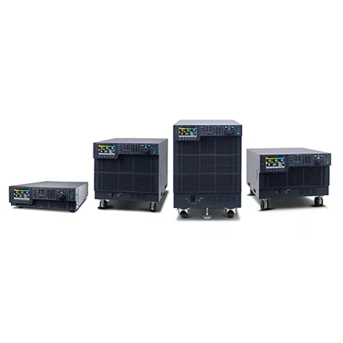
Net weight
(200 V / 400 V) (kg)
|
28
|
47 / 49
|
71 / 72
|
104 / 106
|
|
Net dimension, W x H x D (mm)
|
430 x 129.2 x 667.5
|
430 x 262 x 562
|
430 x 389 x 562
|
430 x 563 x 562
|
|
Overall dimension (with wheel and
safety cover),
W x H x D (mm)
|
440 x 160 x 720
|
445 x 345 x 650
|
445 x 475 x 650
|
445 x 660 x 665
|
|
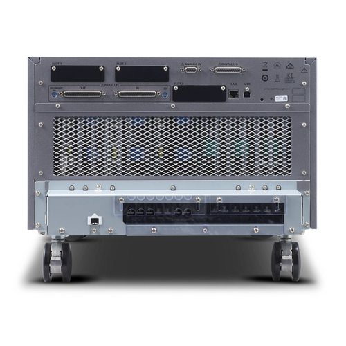
Input terminal
|
M6
|
M5
|
M5
|
M8 (200 V input)
M5 (400
V input)
|
|
Output terminal
|
M6
|
M5
|
M5
|
M6
|
1. Lag in phase due to response
speed not included.
2. Output voltage
at 100 V/200 V, rated
output current, sine wave, load power factor
1, output frequency
40 Hz to 1 kHz.
3. The current
at the minimum voltage within
the allowable variation
range.
4. Output voltage
at 100 V/200 V, rated output current,
sine wave, load power factor
1, output frequency 45 Hz to 65 Hz
|
General
|
All models
|
|
Insulation resistance:
· Primary-to-chassis
· Output-to-chassis
· Primary-to-output
|
500 Vdc, 10 MΩ or more
|
|
Withstand voltage:
· Primary-to-chassis
· Output-to-chassis
· Primary-to-output
|
1500 Vac, 2150
Vdc, 1 minute
|
|
Isolation to ground
|
320 Vrms / 452 Vdc
|
|
Electromagnetic compatibility (EMC)
|
Complies with requirements for the following directives and standards:
EMC Directive 2014/30/EU EN
61326-1 (Class A 1
EN
55011 (Class A1, Group 1 2) Applicable under the
following conditions:
The maximum length
of all cabling and wiring connected to the product must be < 3 m (< 9.8 feet), excluding the cable that
connects to the LAN
|
|
Safety
|
Complies with
the requirements of the following directives and standards: Low Voltage Directive 2014/35/EU 1
EN 61010-1
(Class I 3, Pollution Degree
2 4)
|
|
Environmental conditions
|
|
Operating environment
|
Indoor use, overvoltage category II
|
|
Operating temperature range
|
0 to 40 °C (32 °F to 104
°F)
|
|
Storage temperature range
|
-10 to +60 °C (14 °F to 140 °F)
|
|
Operating humidity range
|
20% RH to 80% RH (no
condensation)
|
|
Storage humidity range
|
90% RH or less (no
condensation)
|
|
Altitude
|
Up to 2000 m (6561.7 feet)
|
1. This is a Class A instrument. The intended use for this product is in an industrial environment. This product may cause interference if used in residential areas. Avoid residential use unless the user takes special measures
to reduce
electromagnetic emissions to prevent interference to the reception
of radio and television broadcasts.
2. This is a Group 1 instrument. This product does not generate
and / or use radio frequency energy in the form of electromagnet ic radiation, inductive
and / or capacitive coupling
for the treatment of material
or inspection/analysis purposes.
3. This product
conforms to Class
I. For safety reasons, ground
the protective conductor terminal of this product.
4. Pollution, in addition to foreign matter
(solid, liquid, or gaseous), may produce a reduction of dielectric strength
or surface
resistivity. Pollution
Degree 2 assumes
only non-conductive pollution will occur except for an occasional temporary
conductivity caused by condensation.